
Designing parts for sheet metal fabrication requires a fundamentally different approach compared to CNC machining or 3D printing. In sheet metal manufacturing, a flat piece of metal is cut, punched, and folded into a 3D structural component. While modern CAD software allows engineers to draw almost any complex geometry, translating those digital lines into physical, cost-effective metal parts is where Design for Manufacturing (DFM) becomes critical.
Failing to optimize your designs for the factory floor often leads to severe material deformation, cracked bends, increased scrap rates, and delayed production timelines. Conversely, a well-optimized DFM strategy not only accelerates the manufacturing process but can drastically reduce tooling and labor costs. In this comprehensive guide, we will walk you through the essential best practices for sheet metal design and highlight the most common mistakes you must avoid.
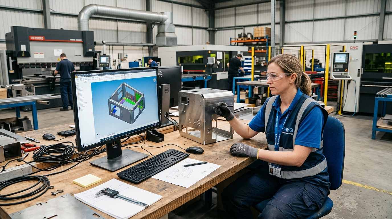
The most fundamental rule of sheet metal design revolves around bending. When a flat sheet is forced into a V-die by a press brake, the material on the outside of the bend stretches while the inside compresses. To prevent the metal from fracturing or warping, engineers must specify the correct inside bend radius.
As a universal rule of thumb, the inside bend radius should be at least equal to the material's thickness (1T). For harder materials like high-tensile carbon steel or certain aerospace-grade aluminum alloys, this minimum radius may need to increase to 2T or 3T to prevent cracking. Furthermore, to keep manufacturing costs low, you should strive to maintain a uniform bend radius across all bends on a single part. This prevents the press brake operator from having to undergo time-consuming tool changes between folds.
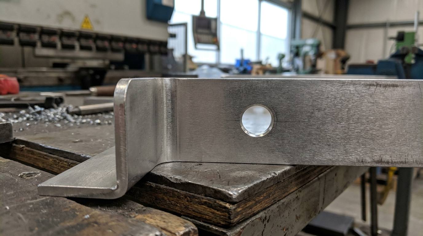
Placing holes, slots, or cutouts too close to a bend line is a classic design flaw. During the bending process, the material near the bend line undergoes extreme stress. If a hole is positioned in this deformation zone, it will stretch into an oval shape, rendering it useless for hardware insertion or structural alignment.
To ensure the integrity of your features, the distance from the edge of a hole to the start of the bend should be at least 2.5 times the material thickness plus the bend radius (2.5T + R). This rule is especially critical when designing complex Custom Sheet Metal Enclosures that require precise alignment of internal motherboards and cooling fans. If a hole must be placed near a bend due to spatial constraints, your manufacturing partner may need to punch the hole after the bending process, which significantly increases secondary machining costs.
When a bend is performed near the edge of a flat sheet, the adjacent material can tear. To prevent this, engineers must incorporate bend reliefs. A bend relief is a small notch cut into the material immediately adjacent to the bend line, providing the metal with the necessary space to stretch naturally.
The width of a bend relief should be at least equal to the material thickness, and its depth should extend slightly past the bend radius. Similarly, applying chamfers or rounded fillets to sharp corners before the metal is cut will not only make the parts safer for assembly line workers to handle but will also improve the adhesion of powder coating treatments.
Even experienced mechanical engineers occasionally overlook the physical constraints of heavy machinery. Below are the most frequent mistakes that disrupt the fabrication workflow:
Specifying Unnecessarily Tight Tolerances: While CNC machining can easily achieve tolerances of ±0.005 inches, demanding the same precision from a sheet metal press brake is both unrealistic and expensive. Unless a specific mounting point requires strict accuracy, rely on standard sheet metal tolerances (typically ±0.015 inches). Over-tolerancing forces the manufacturer to use specialized tooling and increases the scrap rate, which inflates your invoice.
Designing Impossible Closed Geometries: A press brake requires physical clearance for its upper punch and lower V-die to operate. Designing a tall, narrow U-shape or a completely closed box without allowing room for the tooling will make the part impossible to bend. When designing parts like Precision Sheet Metal Brackets, always visualize the sequence of folds and ensure the machine has sufficient clearance to retract after each bend.
Ignoring Hardware Insertion Clearances: Using self-clinching fasteners (like PEM nuts and standoffs) is an excellent way to add strong threads to thin sheet metal. However, placing these fasteners too close to a vertical wall or bend will prevent the hardware insertion press from fitting over the hole. Always consult the fastener manufacturer's datasheet for minimum edge distance requirements.
Deciding how to join multiple sheet metal components is a critical DFM consideration. While robotic and manual TIG/MIG welding provides exceptional structural rigidity—ideal for constructing Heavy Duty Equipment Racks—welding introduces extreme heat. This heat can cause thin-gauge sheet metal to warp, requiring costly post-weld straightening and grinding to restore the aesthetic finish.
Whenever possible, engineers should consider mechanical fastening methods. Designing intersecting tabs and slots, utilizing industrial rivets, or employing self-clinching hardware can drastically reduce assembly time. Mechanical fastening also allows the product to be shipped flat-packed, which significantly reduces international freight costs compared to shipping fully welded, hollow enclosures.
A truly optimized sheet metal design requires a collaborative effort between your product development team and the factory floor. By strictly adhering to DFM principles—standardizing bend radii, respecting hole clearances, and designing for tooling accessibility—you can eliminate bottlenecks before the first sheet of metal is ever cut.
At Huapusheng, our dedicated engineering team provides proactive DFM analysis for every project. We review your 3D CAD files to identify potential manufacturing risks and suggest cost-saving modifications, ensuring your hardware scales flawlessly from prototype to mass production. Submit your designs to us today, and let’s optimize your next manufacturing run together.
What is the most common reason a sheet metal part fails during bending?
The most common failure is metal fracturing caused by specifying an inside bend radius that is too tight for the given material thickness or hardness. Always adhere to the minimum bend radius (usually 1T) to allow the metal to stretch without tearing.
Can I use multiple different bend radii on a single part?
While CAD software allows it, using multiple different bend radii on one part is highly discouraged. It forces the press brake operator to stop the machine and physically change the punch and die tooling for every different bend, which drastically increases your labor costs and production time.
How does laser cutting heat affect DFM?
If cutouts or holes are placed too closely together, the concentrated heat from the fiber laser can cause the narrow strips of metal between them to warp or melt. It is best practice to keep the distance between punched or laser-cut features greater than the thickness of the metal itself.
 Get a Quote Now


 IPv6 Network Supported
Leave A Message
Scan to Wechat :

Scan to Whatsapp :

Hi! Click one of our members below to chat on

 English
 Français
 Deutsch
 Русский
 Italiano
 Español
 Nederland
 日语
 한국어
 Svenska