

 English
 Français
 Deutsch
 Русский
 Italiano
 Español
 Nederland
 日语
日语 한국어
한국어 Svenska
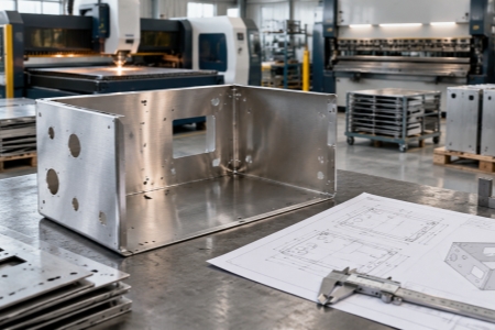
A sheet metal drawing can look complete and still leave important manufacturing questions unanswered. For a fabricator, missing information about material, thickness, bend direction, tolerances, surface treatment, or assembly requirements can lead to clarification requests, revised quotations, or production delays.
For procurement teams and mechanical engineers, a good drawing does more than describe the finished part. It should provide enough information for the fabricator to understand what must be controlled, what can vary, and which characteristics are critical to the application's performance.
This guide focuses on the information that has the greatest impact on sheet metal fabrication, particularly for enclosures, brackets, panels, cabinets, and other fabricated metal components.
1. Specify the Material Grade Clearly
Material selection affects strength, corrosion resistance, forming behavior, welding, surface finishing, and ultimately cost. Writing only "steel" or "stainless steel" is rarely sufficient for production.
| Drawing Information | Example | Why It Matters |
|---|---|---|
| Material family | Carbon steel | Defines basic material characteristics |
| Grade | SUS304 / 316L | Controls mechanical and corrosion properties |
| Thickness | 2.0 mm | Affects cutting, forming and strength |
| Material standard | Applicable ASTM/EN/JIS specification | Reduces material interpretation errors |
If the component will be exposed to moisture, chemicals, outdoor conditions, or corrosive environments, the material requirement should be established before fabrication rather than relying on surface treatment to compensate for an unsuitable base material.
2. Define Sheet Thickness Instead of Relying on Nominal Strength
Two parts made from the same material can behave very differently when their thicknesses differ. Sheet thickness affects bending force, minimum bend radius, part rigidity, weight, and welding parameters.
For example, a bracket specified simply as "stainless steel bracket" leaves several manufacturing variables unresolved. A more useful drawing would identify the exact grade and thickness and provide the critical finished dimensions.
Thickness should also be consistent throughout the drawing package. If a flat pattern, 3D model, and 2D drawing show different thickness values, the supplier may need to stop production until the discrepancy is resolved.
3. Show Bend Locations and Bend Direction
Bending is one of the most common sources of dimensional differences between a CAD model and a finished sheet metal component. Engineers should clearly identify bend lines, bend angles, and important inside or outside dimensions.
| Bend Detail | Information to Specify |
|---|---|
| Bend angle | For example, 90° |
| Bend radius | Inside radius or applicable forming requirement |
| Bend direction | Up/down or defined reference direction |
| Critical bend dimension | Dimension that affects assembly or fit |
When a particular radius is functionally important, it should be stated explicitly. Otherwise, the fabricator may select a practical tooling combination based on the material and thickness.
For projects requiring repeatable cutting, forming, and dimensional control, working with a Precision Sheet Metal Fabrication Service can also help engineers review whether the specified geometry is practical for production.
4. Identify Critical Dimensions
Not every dimension on a sheet metal part requires the same level of control. Treating every measurement as equally critical can unnecessarily increase manufacturing cost and inspection time.
A better approach is to identify dimensions that directly affect assembly, sealing, electrical clearance, mounting, or interaction with another component.
For example, on an electrical enclosure, the position of a mounting hole pattern may be more important than a non-functional external edge dimension. The drawing should make this distinction clear.
For precision applications, engineers can use appropriate geometric tolerancing or clearly defined dimensional tolerances rather than adding unnecessarily tight tolerances to every feature.
5. Define Hole Sizes and Hole Locations Carefully
Holes are frequently used for fasteners, mounting, ventilation, cable entry, hinges, handles, and electrical components. Their diameter and position can have a direct effect on final assembly.
For a production drawing, specify:
- Hole diameter or applicable hole standard
- Hole center location
- Quantity
- Thread specification where applicable
- Counterbore or countersink requirements
- Positional tolerance when required
Repeated holes should preferably be dimensioned from a clear datum or pattern rather than creating a long chain of dimensions. This reduces accumulated dimensional variation and makes inspection easier.
6. State Surface Finish Requirements Separately
"Good surface finish" is not a sufficiently precise manufacturing requirement. Surface treatment should identify the intended process and, where relevant, the appearance or performance requirement.
| Requirement | Example Information | Typical Purpose |
|---|---|---|
| Powder coating | Color reference and finish requirement | Corrosion protection and appearance |
| Anodizing | Applicable grade/color where required | Aluminum surface protection |
| Electroplating | Plating type and required specification | Corrosion and functional requirements |
| Brushed finish | Specified direction or surface | Controlled visual appearance |
It is also useful to identify surfaces that must remain free from visible marks. This is particularly important for front panels, equipment enclosures, and customer-facing components.
7. Explain Welding and Assembly Requirements
A drawing should show which components are welded, how they are positioned, and which welds are functionally important. If the final product requires dimensional control after welding, that requirement should also be communicated.
For fabricated assemblies, useful information can include:
- Weld location
- Weld type
- Weld size where required
- Continuous or intermittent weld requirement
- Visible-side appearance requirements
- Post-weld finishing requirements
- Final assembly dimensions
Not every weld needs a highly detailed specification. The objective is to provide enough information for the fabricator to understand the functional requirement without unnecessarily restricting the production method.
For larger assemblies, this becomes especially important when the finished component must maintain alignment between multiple panels, brackets, or structural members. A clear assembly drawing can prevent problems that are difficult to correct after welding.
8. Include the Flat Pattern or Manufacturing Data When Appropriate
A finished 3D model describes the final geometry, but sheet metal fabrication begins with a flat sheet. The relationship between the finished part and its developed flat pattern depends on material thickness, bend radius, tooling, and the fabrication process.
For this reason, production teams commonly work with CAD files together with 2D manufacturing drawings. When a customer supplies a flat pattern, it should be treated as controlled manufacturing information and checked against the final drawing revision.
For components such as a Custom Metal Sheet Metal Panel, the drawing should clearly distinguish cut features from formed features. Hole patterns, mounting points, bends, material thickness, and surface treatment should all correspond with the latest revision.
9. State the Required Inspection Points
Inspection becomes much more efficient when the drawing identifies what actually needs to be verified. A production inspection plan can then focus on dimensions and characteristics that influence function.
| Feature | Possible Inspection Method | Priority |
|---|---|---|
| Overall dimensions | Caliper / height gauge / CMM where applicable | Assembly-dependent |
| Hole diameter | Plug gauge / caliper | Fastener-dependent |
| Hole position | CMM / fixture / dimensional inspection | Assembly-dependent |
| Bend angle | Angle gauge | Fit-dependent |
| Surface finish | Visual or specified test method | Application-dependent |
For cabinet and frame projects, inspection should also consider the relationship between individual fabricated parts after assembly. A component can satisfy its individual dimensions but still create an assembly problem if accumulated variation is not controlled.
10. Control Drawing Revision and File Consistency
Even a technically accurate drawing can cause production problems if the supplier receives multiple versions of the same part.
Every production drawing should have a revision identifier and revision history. When a dimension, material, hole position, finish, or assembly requirement changes, the revision should clearly indicate what was modified.
The 2D drawing, 3D CAD model, flat pattern, BOM, and purchase order should also refer to the same revision whenever possible. This simple document-control practice can prevent a common manufacturing problem: producing the correct part according to an outdated file.
This is particularly important for a Sheet Metal Cabinet Frame Fabrication project, where several individual parts may need to be cut, bent, welded, fastened, finished, and assembled according to one controlled product revision.
A Practical Drawing Review Before RFQ
Before sending a sheet metal project to a fabrication supplier, engineers and buyers can use the following quick review:
| Check | Ready? |
|---|---|
| Material grade and thickness are defined | □ |
| Critical dimensions are identified | □ |
| Bend angles and important radii are specified | □ |
| Hole sizes, threads, and positions are clear | □ |
| Surface treatment is defined | □ |
| Welding and assembly requirements are clear | □ |
| Inspection requirements are identified | □ |
| Drawing and CAD revision numbers match | □ |
From Drawing to Production
A well-prepared drawing gives a sheet metal fabricator a much clearer manufacturing target. It also allows suppliers to identify potential issues before production rather than after the first batch has been completed.
For projects involving complex formed parts, equipment enclosures, brackets, cabinets, or welded assemblies, the most useful drawing is not necessarily the one containing the largest number of dimensions. It is the one that clearly separates critical requirements from normal manufacturing variation.
At the quotation stage, providing the material, thickness, dimensions, tolerances, surface treatment, assembly requirements, annual or batch quantity, and applicable CAD files gives the fabrication team the information needed to evaluate the process and prepare a more reliable quotation.



 IPv6 Network Supported