
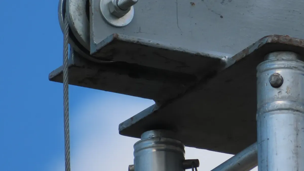
To design and order Custom Heavy Duty Metal Brackets online, you must first define your exact working loads, force vectors, hole configurations, and mounting space constraints. Next, select heavy-gauge sheet metals, prepare your 2D or 3D CAD models, and upload them directly to instant online quoting platforms for immediate fabrication.
Calculate your load needs and add gussets to strengthen high-stress points.
Choose strong materials and protective coatings to prevent rust and bending.
Upload accurate STEP or DXF CAD files online for fast manufacturing.
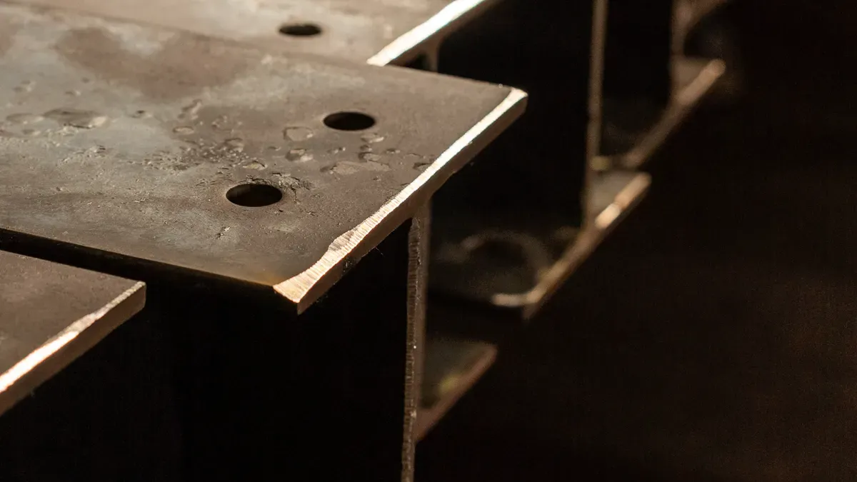
Designing reliable structural components requires careful planning and exact technical parameters. You must convert physical weight demands into precise geometric shapes. Proper engineering prevents structural fatigue, permanent deformation, and equipment failure under extreme operational loads.
You must calculate both static and dynamic loads before manufacturing your components. Static loads represent non-moving weight, while dynamic loads account for vibration, impact, and movement. Calculate the total force distribution across every mounting plane to ensure absolute stability.
Pro Tip: Always apply a safety factor between 1.5 and 3.0 depending on your application. Industrial machinery mountings demand higher safety margins than standard wall mounts.
Identify high-stress points where the bracket bends or connects to support structures. Force vectors concentrate heavy stress directly on bend radii and mounting joints. You can mitigate stress concentrations by adding triangular gussets or vertical stiffeners along the bend angle. These features distribute force evenly and increase rigidity without adding excessive material weight.
|
Load Type |
Primary Cause |
Design Solution |
|---|---|---|
|
Static Load |
Dead weight of equipment |
Increase material thickness |
|
Dynamic Load |
Motor vibration or shock |
Integrate gussets and lock hardware |
|
Cantilever Force |
Overhanging equipment leverage |
Extend flange length and add stiffeners |
For specialized structural applications, such as a Custom Fabricated Industrial Equipment Cabinet Frame, precise load calculation guarantees long-term durability under continuous heavy-duty operations.
Strategic placement of mounting holes ensures maximum load retention and prevents material shear. Maintain a minimum distance of two times the material thickness between hole edges and outer bracket boundaries. Placing holes too close to an edge weakens the surrounding metal.
Avoid drilling holes after laser cutting and bending processes, as post-fabrication modification reduces dimensional accuracy. Instead, program all hole geometries directly into your initial CAD model.
Choose appropriate fasteners based on shear and tensile load requirements:
Grade 8 Hex Cap Screws: Ideal for high-vibration machinery frameworks.
Structural Anchor Bolts: Essential for securing heavy frames directly into concrete foundations.
Countersunk Fasteners: Perfect for flush surface mounts on smooth outer enclosures.
Proper fastener clearance prevents binding during final installation. Incorporate slotted holes if you need alignment flexibility during final assembly.
Creating high-capacity shelving systems demands accurate design and measurement from the start. You must evaluate wall stud locations, wall anchor ratings, and shelf depth. Deeper shelves increase physical leverage, which amplifies the pull force on upper wall fasteners.
When you assemble diy metal shelf brackets for industrial storage or dense workshop tooling, extend the vertical leg to cover multiple mounting points along the stud. This configuration disperses tension forces across a wider surface area.
Engineering custom heavy duty metal brackets online allows you to specify exact flange dimensions, hole locations, and reinforcement ribs tailored directly to your custom layout.
Selecting the ideal material and protective finish prevents structural failure.
Choosing the correct alloy dictates your component's ultimate durability and load limit. Carbon steel offers incredible structural strength for heavy machinery frames. Stainless steel resists harsh environmental conditions and chemicals. Aluminum extrusions provide a superior strength-to-weight ratio for modular structural bracket designs, enabling strong structural support with reduced component weight and higher versatility.
|
Alloy / Grade |
Ultimate Tensile Strength Range |
Yield Strength Range |
|---|---|---|
|
ASTM A36 Carbon Steel |
400 to 550 MPa |
250 to 350 MPa |
|
304 Stainless Steel |
515 to 750 MPa |
205 to 300 MPa |
|
6061-T6 Aluminum Alloy |
290 to 310 MPa |
240 to 275 MPa |
Thicker plate materials handle higher mechanical loads and reduce flex under dynamic forces. However, thicker stock changes your bending parameters during CNC press brake forming. During air bending on a press brake, the inside bend radius scales directly in a 1-to-1 linear proportion with increasing sheet metal gauge thickness. You must adjust your CAD file geometry to accommodate these larger bend radii.
Bare metal degrades quickly without proper surface protection. You must match the finishing process to your operational environment:
🛠️ Quick Tip: Powder coating delivers excellent scratch resistance for indoor machinery frames. Use hot-dip galvanizing or zinc plating to shield outdoor steel components from severe moisture and rust.
When you specify custom heavy duty metal brackets or Custom Heavy Duty Metal Brackets for specialized equipment enclosures, high-grade finishes preserve mechanical integrity and deliver a professional industrial appearance.
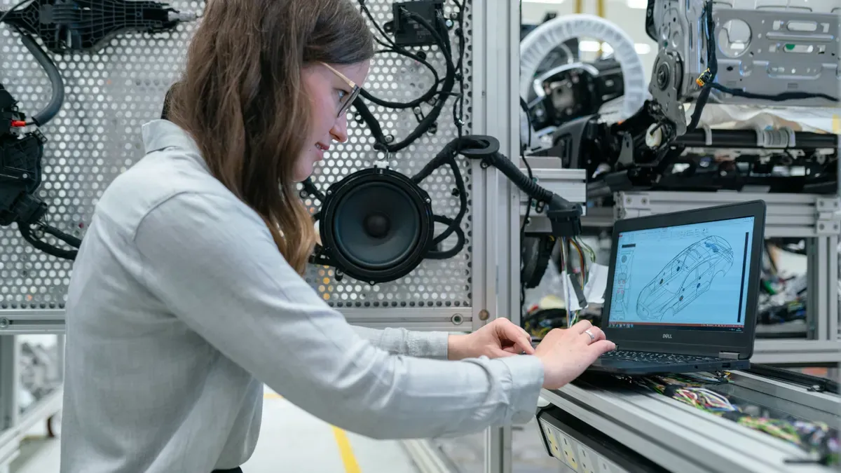
Digital workflows streamline the transition from initial digital design to finished structural hardware. Online platforms accept accurate CAD files directly, reducing manual processing time and eliminating costly communication delays.
You must format your engineering files correctly before uploading them to custom bracket fabrication portals. Digital machinery reads standard 3D file formats like STEP and IGES for complete geometric analysis. Flat profile exports using 2D DXF or DWG formats assist automated toolpathing for flat sheet production.
Follow precise export settings to maintain exact physical proportions:
|
Setting / Requirement |
Action for Export |
Scale Distortion Prevention |
|---|---|---|
|
Drawing Scale |
Model directly in 2D at a true 1:1 real-world size |
Guarantees physical dimensions match CAD geometry |
|
Base Units |
Define units in millimeters before beginning design |
Prevents unit mismatch errors during laser cutting |
|
Unit Conversion |
Convert geometry drawn in inches into millimeters upon export |
Prevents parts from shrinking down to 1/25.4 of their actual size |
Clear CAD models yield reliable physical parts. Apply these key file preparation steps:
Export Scale: Build and export all CAD files at a strict 1:1 true scale, preferably using inches or millimeters.
Clean Geometry: Deactivate or eliminate extraneous construction lines and projected geometry from sketches prior to export.
STEP Export Settings: Work and export at the component level instead of the body level to ensure the STEP format option is available and exported correctly.
Complex assemblies require individual component exports. For instance, designing an OEM Sheet Metal Battery Box Fabrication & Assembly Service requires separate files for every bracket, structural flange, and outer panel to ensure exact laser toolpathing.
Modern web interfaces analyze your uploaded files instantly. These platforms evaluate material volume, sheet thickness, bend counts, and tool paths automatically.
Online custom fabrication platforms offer severe advantages over traditional purchasing channels:
|
Metric / Aspect |
Online Fabrication Services |
Local Machine Shops |
|---|---|---|
|
Quoting Lead-Time |
Immediate or same-day automated quotes |
Manual response taking 3 to 5 business days |
|
Production & Delivery Lead-Time |
Guaranteed 3-day turnaround commitment; 3-day shipping duration |
Up to 2 weeks delay based on shop backlog |
|
Cost Factors & Setup Fees |
Lower costs via automated toolpath generation; no minimum order quantity (MOQ) |
Expensive for low-volume due to high manual setup and machinist labor rates |
|
Pricing Model |
Standardized, transparent, and predictable |
Variable and subject to current workload |
Automated software provides real-time design feedback upon file upload. The system alerts you immediately if a hole sits too close to an edge or if a bend radius violates physical tooling limits. High-speed laser cutters begin cutting the metal sheet instantly after file approval, followed by automated CNC press brakes bending the metal into precise three-dimensional profiles. Streamlined online sheet metal fabrication services handle precise material thicknesses up to 0.125 inches while offering fast turnaround capabilities without minimum order quantities.
Reviewing final digital order proofs ensures your components meet strict physical fitment specs. Standard manufacturing standards govern precision computer-controlled processes. The industrial standard ISO 2768-mK defines general limits. The designation m (medium) sets linear tolerances, while K governs geometric parameters like flatness and perpendicularity.
|
Fabrication Process |
Standard Specification |
Achievable Linear Precision |
|---|---|---|
|
Laser Cutting |
ISO 2768-mK |
±0.1 mm to ±0.2 mm |
|
Sheet Metal Bending (CNC/Press Brake) |
ISO 2768-cK |
±0.2 mm to ±0.5 mm |
Accumulated variations can misalign fastener holes during final installation across complex sheet metal shapes. Evaluate these factors during your final design review:
|
Fabrication Factor |
Impact on Fitment & Hole Alignment |
Recommended Design Mitigation |
|---|---|---|
|
Multi-Bend Profiles |
Angular errors (~0.5° per hit) accumulate across bends, shifting hole locations on final flanges by up to 1/16" |
Dimension critical features from a single functional datum rather than chaining dimensions |
|
Post-Processing (Coating) |
Powder coating adds 3–7 mils of material, closing clearance gaps and shifting hole alignment |
Account for finish thickness by sizing clearance holes for 'after-finish' conditions |
|
Proximity to Bend Lines |
Placing holes within 2T + R distorts circular holes into ovals as metal stretches during forming |
Ensure holes are positioned outside the plastic deformation zone (further than 2T + R) |
|
General Part Shifts |
Typical shifts of ±.020" across bends create forced, stressed assemblies leading to damaged threads |
Replace standard round holes with slots to serve as self-aligning 'landing zones' |
💡 Design Tip: As the number of fasteners in a pattern increases, total accumulated error requires tighter manufacturing limits for individual holes. Replace standard circular holes with slots to create self-aligning landing zones across multi-bend profiles.
Careful file preparation and tolerance verification guarantee that your custom heavy duty metal brackets arrive ready for immediate installation into your equipment frames.
Designing custom heavy duty metal brackets requires clear structural specifications, high-strength metals, dynamic finishes, and accurate CAD uploads. Review this pre-flight checklist before submitting your order:
Verify dimensional tolerances and hole alignments
Confirm appropriate bend radii for sheet thickness
Specify protective surface coatings
Check hardware size and fastener compatibility
Upload your CAD models to our online fabrication platform today to receive instant pricing and accelerate your project workflow!
💡 Need Quick Answers? Review these frequently asked questions before submitting your custom bracket CAD models online.
Upload 3D STEP or IGES files for complete geometric evaluation. You can also submit 2D DXF or DWG files for precise flat-pattern laser cutting.
Select protective surface finishes based on your operational environment. Apply durable powder coating for indoor equipment frames or specify zinc plating for outdoor applications.
Slotted holes provide alignment flexibility across complex bent flanges. They absorb minor manufacturing tolerances and prevent fastener binding during final equipment assembly.
 Get a Quote Now


 IPv6 Network Supported
Leave A Message
Scan to Wechat :

Scan to Whatsapp :

Hi! Click one of our members below to chat on

 English
 Français
 Deutsch
 Русский
 Italiano
 Español
 Nederland
 日语
日语 한국어
한국어 Svenska