
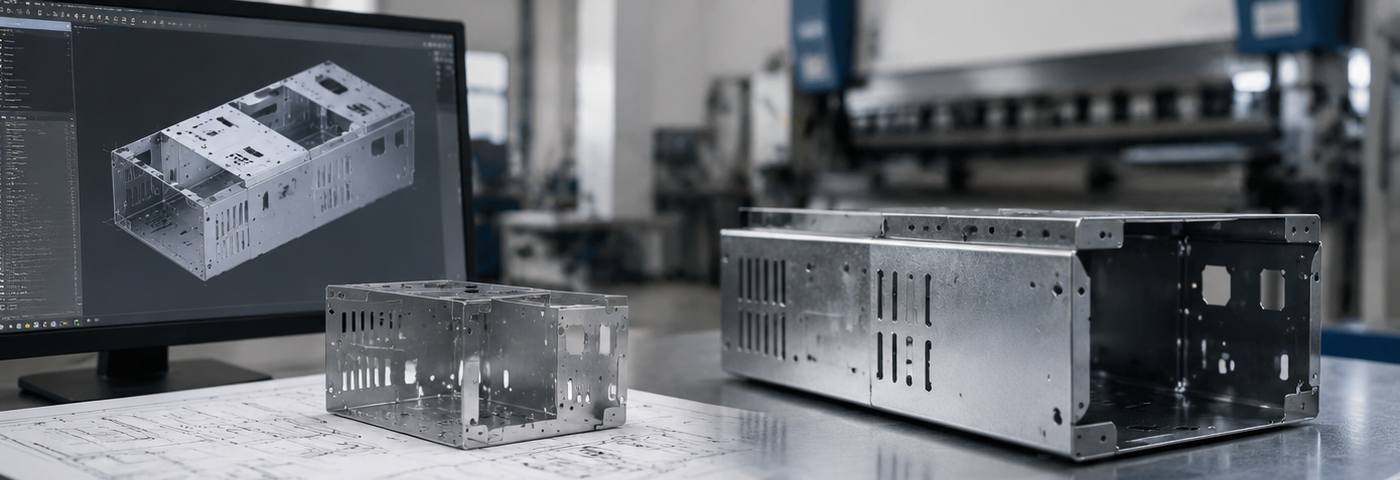
In the industrial hardware sector, the gap between a 3D CAD model and a physical, cost-effective product is bridged by Design for Manufacturability (DFM). A design that functions perfectly in simulation can often carry unnecessary manufacturing costs if it does not account for the physical behavior of metal during laser cutting, bending, and welding. Addressing these variables at the engineering stage prevents costly revisions and accelerates the time-to-market.
Optimizing a part for High Precision Metal Enclosure Fabrication is not about compromising the design intent; it is about aligning the geometric features of the part with the specific capabilities and tooling constraints of the factory floor. This document details the critical DFM principles that engineers must apply to sheet metal parts to ensure structural integrity while minimizing processing time.
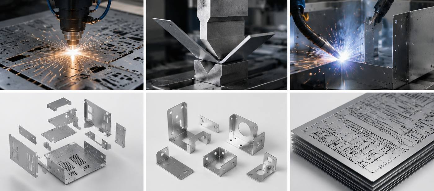
When sheet metal is bent, the material on the outside of the bend axis undergoes tension and stretches, while the inside experiences compression. If a bend is located too close to an edge or another feature without proper relief, the metal will tear, deform, or warp the adjacent geometry. Bend relief cuts must be incorporated into the flat pattern to isolate the bending stress.
A standard rule for DFM is that the depth of the bend relief should be at least equal to the material thickness plus the bend radius, and the width should be at least equal to the material thickness. Furthermore, designing a flange that is too short for the V-die on the press brake will make it impossible for the machine to grip and form the metal accurately. A CNC bending process requires a minimum flange length to ensure the metal bridges the die opening stably during the downward stroke.
| Material Thickness (T) | Recommended Inside Radius (R) | Minimum Flange Length (L) | Minimum Bend Relief Width |
|---|---|---|---|
| 1.0 mm | 1.0 mm | 4.5 mm | 1.0 mm |
| 2.0 mm | 2.0 mm | 8.5 mm | 2.0 mm |
| 3.0 mm | 3.0 mm | 12.5 mm | 3.0 mm |
| 5.0 mm (Heavy Gauge) | 5.0 mm - 6.0 mm | 22.0 mm | 5.0 mm |
Placing holes, slots, or cutouts too close to a bend line or the edge of the material introduces severe manufacturing risks. When a hole intersects the deformation zone of a bend, it will stretch into an oval shape, rendering it useless for precise hardware insertion (such as PEM nuts or standoffs). As a strict engineering guideline, the distance from the edge of a hole to the start of a bend must be at least 1.5 times the material thickness plus the bend radius.
Similarly, placing holes too close to the outer edge of the blank causes edge bulging. While advanced laser cutting mitigates mechanical stress compared to traditional punching presses, the thermal concentration in narrow webs of metal can still cause localized warping. Maintaining a minimum distance of at least 1.5 times the material thickness between any hole and the material edge ensures dimensional stability.
| Feature Placement | DFM Rule of Thumb | Risk if Ignored |
|---|---|---|
| Hole to Bend Line | 1.5T + Bend Radius | Hole distortion (ovaling), failed hardware insertion |
| Hole to Outer Edge | 1.5T (Minimum) | Edge bulging, weak structural web |
| Hole to Hole Spacing | 2.0T | Thermal warping, tooling interference |
| Minimum Hole Diameter | 1.0T (Laser) / 1.2T (Punch) | Tool breakage (punching), slag accumulation (laser) |
In large-scale assemblies like an Industrial CNC Bent Electrical Cabinet Chassis, multiple sheet metal parts must align perfectly for assembly. Tolerance stacking occurs when the acceptable margin of error in individual bends accumulates across a large part, causing the final mounting holes to misalign. Relying entirely on the press brake operator to hit a ±0.1mm tolerance across five consecutive bends is an expensive and unstable production strategy.
Effective DFM accounts for tolerance stacking by utilizing self-fixturing designs. Incorporating tab-and-slot geometry into the flat patterns allows the metal parts to interlock precisely before welding, removing human error from the alignment process. Additionally, utilizing slotted holes on one side of a mating assembly provides necessary compliance, allowing bolts to pass through even if the overall bent dimensions fluctuate by a fraction of a millimeter.
The cost of raw material often accounts for more than 40% of the total unit price in custom metal fabrication. Parts with irregular, sprawling geometries generate immense amounts of scrap when nested onto a standard 4x8 or 5x10 foot metal sheet. For instance, engineers must evaluate if a complex, single-piece structure can be redesigned into basic rectangular panels and Custom Laser Cut Sheet Metal Brackets that are subsequently spot-welded or riveted together.
While adding a secondary joining operation (like welding) incurs a labor cost, if the redesign improves the laser nesting yield from 60% to 85%, the material savings on a production run of 1,000 units will far outweigh the assembly labor. Designing flat patterns that resemble basic geometric shapes (rectangles, L-shapes) allows programming software to interlock the parts tightly on the raw sheet, driving down the per-unit material expenditure.
 Get a Quote Now


 IPv6 Network Supported
Leave A Message
Scan to Wechat :

Scan to Whatsapp :

Hi! Click one of our members below to chat on

 English
 Français
 Deutsch
 Русский
 Italiano
 Español
 Nederland
 日语
日语 한국어
한국어 Svenska